MICHAEL C. VILLARMA JR., EIT
Arctic Cat Composite Suspension System


ABSTRACT
Snowmobile technology is constantly evolving and incorporating new ideas into products for the consumer to enjoy. After market manufactures are competing among themselves for the top position in suspension technology, yet none have broken the boundaries and really pushed to the next level, until now. The objective of this design was to provide the consumer with a lightweight and simplistic suspension system that would meet the performance demands of the consumer market. In order to meet the strength to weight ratio requirements of this design, composites were implemented to provide the necessary structural strength for the overall system. A one piece carbon fiber sub frame is the first of its kind and provides a foundation for all other components to fasten too. By replacing structural materials that were initially made from a high strength steel with a light weight carbon fiber, the weight savings are substantial and can be observed throughout the system. In order to determine the success of this design, a series of tests both on and off the vehicle were performed to accurately describe the behavior of the material under load. 3 point bending, load analysis, and weight comparison are examples of the test processes that will provide conclusive data on the overall performance of this design.
INTRODUCTION
Motivation:
This project was motivated by a need for a lightweight rear suspension system that meets snowmobile performance standards without sacrificing strength and dependability. There are several companies producing bolt in aftermarket kits, but none that combine the use of composite materials and alloys. We hope to design a suspension system that will sustain the abuse of heavy impacts and sudden changes of load distribution without the use of a heavy gauge steel.
Function Statement:
This device will allow for a controlled transfer of energy between the ground and chassis of a snowmobile. The applied load from uneven terrain will be distributed along the length of a one piece composite backbone. The forces exerted on the backbone will be transmitted directly to the shock absorber and aluminum link arm assembly through front and rear mounts. The shock absorber will control the rebound and dampening properties associated with the forces. This device needs to perform the above tasks while fulfilling the requirements listed below.
Requirements:
In order for this device to function as designed, there are some basic requirements that need to be fulfilled:
-
Must weigh less than the Arctic Cat M Series OEM suspension system of 45 lbs.
-
Sustain maximum load in temperatures of 32˚F +/- 32°
-
Withstand forces up to 300 Kilo Newton’s in vertical drops.
-
Must transfer load between ground and chassis smoothly.
-
Bolt into existing chassis (2006-2011 Arctic Cat M-Series) without alteration.
Engineering Merit:
Several aspects of this design will require a large amount of calculated analysis. Forces and moments in equilibrium, ∑Fx=0, ∑Fy=0, ΣM=0 [1], will be utilized to determine the reaction forces at the given mounting locations. It will be crucial to know the maximum forces applied at these points so that during our design we can determine the dimensioning of mounting brackets. This will ensure the structure will not fail under load. The normal stress, σ = P/A, that occurs in the backbone sub structure will be calculated and accounted for so that during the construction phase of our backbone, we will know the appropriate material size, layering pattern, and tolerances at which the backbone will need. In addition to normal stress, the shear stress in crucial areas such as the pivot point on the rear arm (See Appendix A, pg. 24). The shear stress, τ = V/A, of the hardware used in this pivot point will need to be calculated to determine the quality and hardness of the materials used for the pin. The flexure formula, σ = Mc/I, will be applied in the design of the composite backbone to account for the bending stress that will occur.
Scope of Effort:
We will be designing all features of this device except for the shock absorber and hardware which will be provided. Modern shock technology is a science in its own and we wanted to focus more on the structural and geometry aspects of this design.
Success Criteria:
The success of this device will be based on the requirements fulfilled and performance of the system during standard vehicle use. Performance of device during use will be observed through Point of View cameras which can be further analyzed to determine components or areas that need improvement. A rider survey will also be conducted amongst people with a riding back ground. A rubric will be constructed where participants can rate performance characteristics 1-10 of the system (see Appendix pg. 45).
Benchmark:
There are multiple companies making aftermarket suspension assemblies that improve the performance over the stock ride. K-MOD [2] suspension assemblies is one of the top competitors in the market and provide and excellent product for the consumer. However, they have still retained the scissor style linkage that requires several more components. By eliminating the need for more components, we can construct a lightweight system with the structural properties required to perform adequately.
Optimization:
By incorporating the usage of composite materials, we will replace components that are constructed of allow materials, with a composite, optimizing the strength to weight ratio of the overall structure. We will do this through the use of static, dynamic, and stress analysis methods to determine the proper dimensions of the system.
The geometry of suspension systems on the market require the use of several linkage assemblies which introduce friction, binding, and alignment problems due to use. We plan to optimize the overall geometry of this system by simplifying the linkage systems for a smoother overall transition between maximum and lower limits.
DESIGN & ANALYSIS
Approach:
This design was inspired by the need for a simple, lightweight suspension assembly designed for the backcountry. In order to accomplish this goal, a composite material was required and a simplification of linkage components and geometry alterations would need to occur. The results should yield a lighter overall structure with smoother transitions zones. Multiple sketches were created until a final drawing was approved for analysis.
Description:
Our design will consist of four main components:
The backbone will be made of a carbon fiber reinforced composite, to ensure that we are providing enough rigidity to support the assembly. This component will need to withstand the distributed load due to impact, provide an attachment point for link arm and shocks, and support a rotational track speed up to 70+ mph. Our analysis will be based off a 100 foot or 33 meter drop resulting in a 300 KN impact force, which will be used as a designated impact force the system can withstand.
The mounts that will be machined from a 6061-T6 4” x 3” solid aluminum block. The front and rear mounts will saddle the front and rear shocks and allows the link arm and shock absorbers to be fastened to the backbone. The mounts will be fastened to the backbone using several socket head bolts and bushings (see Appendix B, pg. 24).
The link arm, which connects the rear mounting location to the forward mounting location will be made of 6061-T6 1 ½” aluminum extruded tubing. This component will need to be welded using a tungsten inert gas system and will be coated with a corrosion resistant powder coat. The link arm is subjected to axial forces and will be engineered to withstand the maximum force at impact.
For rebound and dampening control, we will be using two Fox Shox Air Float shocks that are adjustable with air pressure. These shocks will provide us with the adjustability and control we will need in order to ensure proper functionality. In order to keep the project within scope, it was best to outsource this portion of the suspension assembly.
Description of Analyses:
Backbone:
There are several analyses procedures that will occur throughout this process and we first start with determining the maximum impact force at which our suspension assembly will be subjected to. This force can be determined through analysis by utilizing the Energy equation [4], K.E. + U + W = 0 (Appendix A, pg. 16) and the relationship between Work and Kinetic energy, W=∆K.E. The maximum impact force will be calculated from a 33m fall giving us a value for Fmax of 300 KN. The impact force, is distributed along the bottom side of the backbone which will have 1.65 meters in normal contact with a flat surface. This gave us a 175 KN/m distributed load that we could analyze for internal forces, locations of key point loads, and internal moments.
We constructed a simple static analyses (Appendix A, pg. 17) of our suspension assembly to determine reaction forces at mounting locations. We modeled our analysis similar to a beam for simplification purposes. Summing forces in the X and Y direction, we were able to determine the X and Y components of the forces at specific mounting locations. The forward mounting bracket will undergo a 191 KN normal force, while the rear bracket must withstand up to a 98 KN force normal to the backbone.
The maximum shear and moment within the backbone structure is required in order to utilize our stress equation, σ = Mc/I [1]. Using the Method of Sections [1], a technique used in static analysis, the backbone was sectioned off at specific locations to determine the internal shear and moments at those locations. Our maximum shear (89 KN) and bending moment (29 KN*m) occur at the forward mounting bracket. A shear and moment diagram was constructed (Appendix A pg. 20) for a graphical representation of the forces and moments within the backbone.
The top and bottom surfaces will have the highest amounts of stress and gradually decline towards the center of the material (see Appendix A pg. 21). We measure this location from the X axis of our backbone and use this as our value for c in our stress formula. For a starting point, we are going to first analyze a ½” thick backbone structure, which will give us c = .25”.
The moment of inertia of the backbone will now need to be determined using the same ½” thickness as used for determining c. The backbone is rectangle in shape measuring 9.25” wide (X direction) and .5” tall (Y direction). To calculate the moment of inertia, we use the equation bh3 [5], where “b” is equal to 9.25” and “h” is equal to .5”. Plugging these numbers into the equation, we get a result of IB.B.=.09635 in4.
Once all the factors for the stress formula were determined, a maximum bending stress was found equal to approximately 687 KSI (Appendix A pg. 21). Using this information, we were able to determine a suitable material to use for the construction of the backbone. Hexcel im7 carbon fiber with a ½” Aramid honeycomb core has an ultimate tensile strength of 747 KSI [6] which exceeds the maximum bending stress of 687 KSI. This material in our application with yield a factor of safety of 1.08.
Link Arm:
The link arm will be subjected primarily to axial forces during operation. These forces will induce an axial stress on the link arm and must be accounted for in order to optimize the link arm for weight and strength characteristics. Our analysis begins by examining joint A (Appendix A pg. 22) where the link arm, rear shock, and rear mount intersect. Equilibrium equations provided the necessary tools to determine the axial force the link arm is subjected to during maximum impact. The axial force in each member of the link arm is equal to 36 KN. This force was then used to determine the axial stress, σ = P/A in each member of the link arm. 1” O.D. by .125” thick tubing was the first material size we examined and calculated the stress to be 305 MPa (Appendix A, pg. 23). We were interested in using 6061-T6 extruded aluminum tubing for the construction of the link arm due to budget limitations. This material has an ultimate tensile strength of 290 MPa [7], less than the required value for the 1” tubing. It was necessary at this point to decrease the axial stress in the link arm by increasing the cross sectional area to ensure at least a factor of safety of 1. This was done by increasing the outside diameter of the tubing to 1.5”. By increasing the diameter, we managed to lower the stress by 33% to 197 MPa. This axial stress is below the ultimate tensile strength for 6061-T6 and provides a factor of safety of 1.5.
Front and Rear Mounts:
The purpose of the front and rear mount is to transfer the impact load from the backbone directly to the shocks. We will model the mounts as a rigid component connected to the backbone that is subjected to a shearing force. Our main concern with the mounts is the shear force that is expected to occur at the mount locations. The largest shearing force induced by an impact occurs at the front mount and will result in a 213 KN force in the normal X direction. There is a total of 6 bolts securing our front mount to the backbone, and each of these bolts will be subjected to a 36 KN shearing force (Appendix A, pg. 25). We used the shearing force in each bolt and divided that force by the area of the bolt to determine the shear stress in each bolt. Using the cross sectional area of a 3/8” and the shear force induced during impact on a single bolt, we determined the shear stress of this bolt to be 758 MPa or approximately 125 KSI (Appendix A, pg. 25). The stress caused by shear requires the use of 6-3/8”-16 x 1” Grade 8 bolts with nyloc fasteners with a yield stress of 130 KSI. With this application we will have a factor of safety for the front mount bolts of 1.1.
Failure Modes:
During normal operation of the device, a large amount of stress will be induced to the carbon fiber backbone structure. This was taken into consideration during the design and analysis phase of this project. However, our analysis is simply a prediction of how the component will perform, not the actual performance. There are several variables such as weather conditions the device may experience, terrain obstacles (e.g. rocks, trees), that cannot be accounted for. If the suspension assembly enters failure mode, the first component to fail will be the backbone structure. The component will fail due to exceeding the limit of maximum bending stress of our carbon fiber structure (see Appendix pg. 21). Others have conducted similar research by subjected composites structures to bending stress such as S. Kichannagari. In the research conducted by S. Kichannagari’s, the composite structure yielded at approximately 100 KSI (see Appendix F pg. 43). In our analysis, during maximum impact the backbone would be subjected to nearly 800% more stress than the composite material Kichannagari and his colleagues tested [3]. If our material performs in a similar manner, we would expect a fracture along the tail end of the backbone component after the material yielded at 100 KSI.
METHODS & CONSTRUCTION
Exoskeleton:
We will begin construction of our prototype by first assembling an exoskeleton representing the shape of our backbone. The exoskeleton will be constructed from plywood. It is important that the curvature of the mold matches the curvature of the existing rails that are currently used in the stock rear suspension. This will account for no change in the approach angle of the track allowing us to use the original track. To do so, the curvature of the existing rails will be transferred to a large sheet of paper and cut out. Three runners will be cut out of the ½ inch plywood. These runners will be capped with a sheet of ¼ inch plywood the full length and width of the backbone. In order to produce a clean, smooth and desirable mold, we will need to prepare the exoskeleton for fiberglass. We will do so by following these guidelines:
-
All surfaces must be smooth and free of slivers, dimples, or debris.
-
Sharp edges and corners should be rounded to ensure the mold will release from the exoskeleton without becoming damaged.
-
A wax or similar agent will be applied to the exoskeleton to help with releasing the mold.
Mold:
The mold will be constructed primarily from fiberglass and resin. Two layers of cloth woven mat will be cut in the full length and width of the backbone. These layers of cloth will provide the strength needed to sustain the carbon fiber that will be applied to the mold. Once the fiberglass is cured, it will be removed from the wooden exoskeleton and begin being prepped for the carbon fiber. Any flaws within the mold will need to be sanded and smoothed.
Backbone:
We will be using 3 basic materials in our composite backbone structure.
-
Polyurethane Matrix
-
Carbon Fiber Cloth
-
Aramid Honey Comb Core
In order to develop the strongest bond of our composite materials, we will need to ensure:
-
Proper mixing ratios and cure times must be followed
-
Carbon fiber cloth must be fully saturated with polyurethane resin
-
All presence of air must be removed from system.
The first step to beginning the construction of the backbone is to cut our material to size. The carbon fiber will need to cover the entire length and width of the backbone. When cutting the material, a + ½ inch tolerance will be added to the length and width dimensions (see Appendix B pg. 33). This is required to ensure a full overlap of material around the perimeter of the backbone. We can now begin laying our composite materials into our mold (see footnote [1]). This procedure will begin with a layer of polyurethane resin, followed by a layer of Hexcel IM7 [6], aramid honeycomb core, and another layer of the carbon fiber. Once all cloth has been saturated, the mold will be placed inside the vacuum bag to remove air from system. Allow the mold to remain in the vacuum bag until proper cure time is reached. After curing, the backbone will be removed from the vacuum bag and inspected. We will be looking for imperfections (e.g. air bubbles, unsaturated material) and trimming edges if necessary.
Link arm:
The link arm will be constructed from 6061-T6 1 ½” O.D. x .125 thick extruded aluminum tubing. Tubing will be cut to the required dimensions (Appendix B, pg. 37) An AC/DC TIG Welder with a tungsten electrode and 4043 welding rod as a filler will be used to assemble the link arm. All joints require solid welding (no skip or pass) and will need to be properly cleaned before finish coat is applied. Once the link arm passes dimensional inspection, it will be powder coated with a gloss black finish to increase corrosion durability as well as visual appeal.
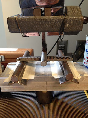
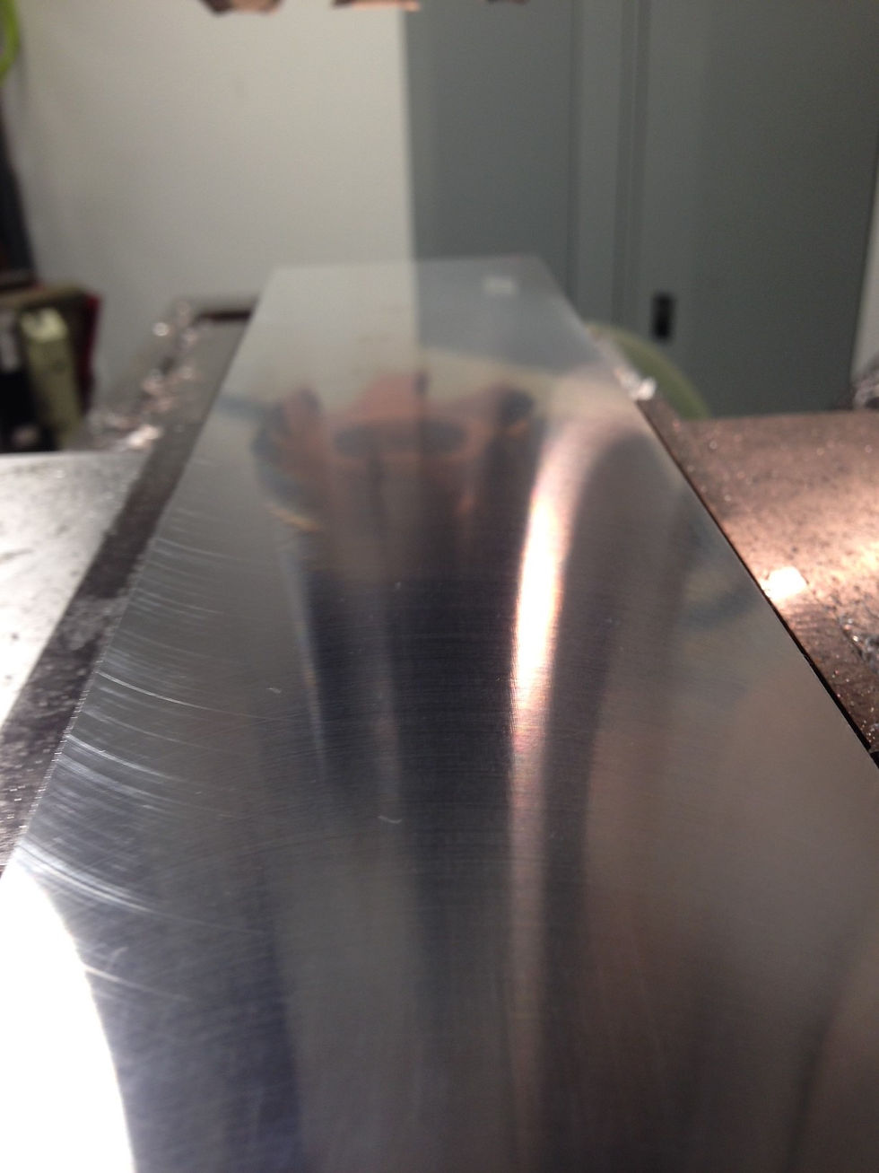
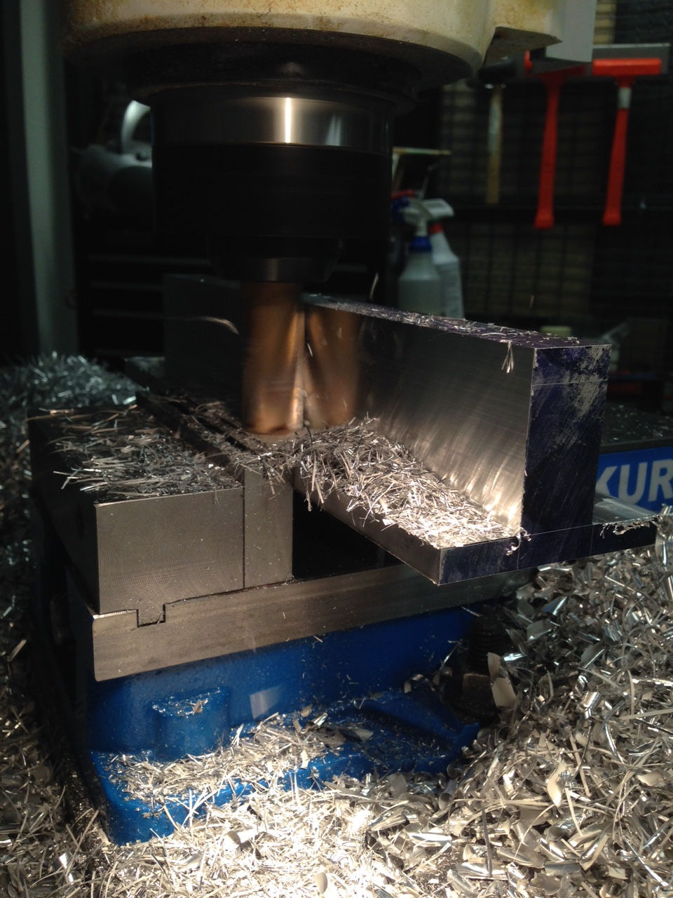
Mounting Brackets:
In order to securely fasten our backbone structure to the chassis of our snowmobile, we will be machining brackets from a 6061-T6 aluminum alloy for structural and strength purposes. The material will be milled from a solid 4” x 3” block of aluminum. The block will be cut to the approximate size the drawing calls for using a horizontal band saw. We can then apply a layer or layout dye to our part and dimension accordingly. Once the layout lines are scribed onto the material, we will begin milling the mount in one of the milling machines available in the machine lab.
[1] Proper ventilation and respiratory precautions must be taken when working with polymer resins.
TESTING METHODS
Material Testing:
Prior to construction, a series of bending tests will be conducted using the Instron 1011 equipped with a 3 point fixture used for bending analysis. Three core samples will be tested using different combinations of Hex Cell ½” board, carbon fiber weave, and polymer resins. In order to determine the appropriate combination of mat and resin, the three samples will be subjected to a maximum bending moment that will result in a “failure” point that correlates to that moment. Samples will begin with 1 layer of mat. Our bending moment equation σ = Mc/I can now be used to find the maximum bending stress of each sample. The sample with the combination that exceeds the maximum bending stress (687 KSI), will move on to the next testing parameter.
All materials will be subjected to a low temperature environment (32°F ). The approved composite combination will now be placed in a freezing environment for 3-5 hours and monitored. The component will then be removed from the freezer and subjected to the same tests as described above. The results will then be recorded for comparison.
Performance Testing:
Weight Test-
This test will consist of a weight comparison between a standard Arctic Cat OEM suspension assembly vs. the composite suspension assembly we designed. A digital scale accurate to the nearest tenth of a pound will be used for measuring. The scale must be within the last calibration date and have a way to suspend each assembly.
Fitment Test-
This test will be judged based on the ease of installment into a 2005-2011 Arctic Cat M series chassis. One snow machine is available at this time for testing. We are interested in time required for install, clearance issues, and ease of install. To document this data, we will be performing this install while a stopwatch records start to finish time.
Load Testing-
The backbone of our suspension assembly is designed to withstand a 100 foot vertical drop. In some cases, this type of impact occurs in extreme circumstances. However, in order to safely test the durability of our design, we will not be undergoing 100 foot impacts. Several hours of testing will be conducted in various conditions in the Central Washington area wilderness. We will capture footage of the suspension in motion using POV cameras to evaluate the performance of the suspension.
Endurance Testing-
In order to this test to be considered successful, a total of 5 hours of riding time must be achieved without failure.
PROJECT MANAGEMENT
In order to organize this project, a budget and schedule have been implemented to ensure overall success. With a project of this size, there is a risk that is taken which may induce sudden changes to the schedule and or budget. These unexpected changes will be accounted for in our schedule with “catch-up days”.
Budget:
An itemized parts list was created with designated call out numbers for reference to establish a tentative budget for this project. The itemized list can be viewed in Appendix C. Call out numbers refer to the number associated with that part in the exploded view of the assembly in Appendix B. There may be small value items (e.g. brushes, containers, misc. fasteners) that have been overlooked in the design phase of this project. A specific dollar amount was set aside to account for these unexpected costs and can be found in the itemized list under “Application Materials”. Total material costs for this project are $1127.80 including all components necessary to complete design.
All material processing (e.g. welding, machining, and composite layup) will be conducted in house at the Hogue Technology building. The machine shop and metallurgical lab will provide the necessary tooling and environment to complete these processes. Since no labor will be outsourced, a large portion of the budget will available for other costs. A total of 150.5 hours are estimated from start to finish prototype. If we had to outsource this labor at an average labor rate of $100/hr., an additional $15,050 would need to be incorporated into the budget to accommodate this cost.
Funding for this project will be provided by a board of members that have been asked to donate any materials or parts listed in our itemized parts list. We are hoping to see a positive response from companies in the industry, encouraging and pushing new technology that will benefit everyone involved. With this positive response and encouragement, we hope to be able to secure several donations that will help with the build phase of this project.
Schedule:
A tentative schedule that is subject to change was created to help organize this project and ensure adequate time for the design, development, and testing of our suspension assembly. This schedule is constrained by the time frames provided by the MET 495 Senior Project Instructors, with a required completion date of June 1, 2015. The schedule is located in Appendix D and can be viewed for further details.
Milestones:
There will be several milestones along the design phase of suspension assembly. The first milestone, which will be the foundation for all processes afterwards, is the completion of the composite backbone structure. This process will be the most crucial process due to the nature of the structure and the material properties (e.g. strength, rigidity) required to continue the assembly. The second milestone will be the completion of the front, rear, and idler wheel mounting brackets. The bulk of material processing time will be used to complete this milestone resulting in four components that will be ready for assembly to the backbone frame. The third milestone will be the completion of the link arm assembly. The completion of the link arm will be the final machined component needed to complete our assembly. Without a complete link arm, other components such as shocks, will not be able to be assembled to our backbone.
DISCUSSION
The initial intent of this project was to design a simplistic, functional, lightweight suspension system for a snowmobile that would be made from strictly composite materials. The first design we created was a one piece composite skid that would utilize the material properties (e.g. elasticity) to perform the transfer of impact from the ground to the rider. After the initial design, analysis of the structure took place. We found that the impact forces the assembly would undergo exceeded the maximum elasticity of the material resulting in a broken component. At this point, a need for a re-design was required and the current assembly found in Appendix B was the solution.
Instead of relying on the material to do the work, we are incorporating 2 Fox Shox to transfer the impact force to the chassis. By integrating the shock work into the system, we were able to drastically change the composite skid design to the “backbone” design we have now. Not only did this adjustment allow the project to continue, we were able to utilize a thinner material for the backbone. This reduction in material negates a portion of the additional weight added to the system by the introduction of 2 shock absorbers.
With the design change came a larger overall suspension assembly. More components were necessary in order for the design to work properly (e.g. link arm, mounts) which made for more design analysis than originally intended. The link arm structure needed to be strong enough to support the structure during a maximum impact load, but light enough to meet the system weight requirement of 45 lbs. or less. In order to achieve this, we optimized the diameter of the tubing as well as the material used to build the link arm. By using a more affordable material (6061-T6) an increase in weight occurred. Titanium was considered as first but due to budget reasons, we opted to go with the 6061 aluminum tubing.
There was an initial concern about securing the front and rear mounts to our backbone. Our analysis showed, that under maximum conditions the mounts were under a severe amount of shear stress. Such that the thickness of the material required to distribute the stress would interfere with our link arm design. We were able to solve this problem by slightly modifying the mounts themselves. Instead of using 4 bolts for each mount, we increased the amount of bolts to 6. This increase in mounting hardware essentially increased the surface area and distributed the shear force introduced by impact.
CONCLUSION
A snowmobile suspension has been conceived, analyzed, and designed that satisfies the function requirements as described in the opening of this proposal. Parts have further been designated, sourced, and budgeted and are pending acquisition upon receipt of sponsorship funds. With this information, this device is ready to be created. Construction will begin once all funding has been received and materials have been ordered.
This project satisfies the requirements listed in the Senior Project metric and are as follows:
-
Having substantial engineering merit in structural and material analysis.
-
Size and cost of the project is within the parameters for means of completion.
-
Is of great interest to the principal investigator.
ACKNOWLEDGEMENTS
This project will be managed primarily by myself with the guidance from Dr. Craig Johnson, a Professional Engineer who is head of the Mechanical Engineering department at CWU, and Professor Charles Pringle who has a Master’s in Mechanical Engineering Technology. Both mentors have an extensive background in engineering design and will be involved in overseeing this project as it continues.
As this project continues, the need for funding will be accomplished through the use of sponsorships. These sponsorships will need to be completed by February 4th, the start of the design phase of our project. If money from a sponsor is not received in time to complete the materials order, the remaining funds will come from myself in order for the project to remain on schedule.